Controls on a Robot Cell: A Recent Project
We recently completed a robot cell project for a machine manufacturer which was the result of collaboration between a few teams. Our customer designed and built the machine. Two specialists designed the two stations within the cell. The Patti Engineering team was responsible for the controls and robot programming, debugging, and onsite installation.
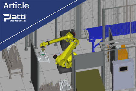
This robot cell included a grinding station and an inspection station as part of a production line for shock towers. The operators load the shock tower onto the nest. The robot picks it up and drops it off at a grinding cell to grind the casting. Then, the robot moves the part to an inspection cell. Using the results of the inspection, the robot sorts the part into one of two locations for good parts and bad parts.
To begin the project, we completed a reach study using Fanuc’s ROBOGUIDE simulator. Given the number of places that the objects would be moving, it was prudent to ensure the chosen robot would reach all places in all of the positions required. If you’ve ever programmed a robot, you probably know that depending on the wrist angle and the length of the robot, the robot sometimes does not reach as far as expected. That would be a very expensive discovery after the machine had been built! However, in this case, the choice of robot – the Fanuc R-2000iC/125L – was confirmed and the teams were able to move forward confidently.
The main controls hardware on the project was a Siemens S7-1500 PLC, chosen for the speed and size of the memory it offered, and a Siemens Comfort Panel HMI. To connect the other hardware, we ran a Profinet connection to an IO-Link master block. The IO link was used to distribute the part-presence sensors, and stack lights. The IO link was chosen for its ease of configurability.
The standard pick and place movement was complicated slightly by the number of different types of parts that came through the area. Not all parts would be the same size or shape. Therefore, we used the barcodes, laser-etched into each part, to give data to the robot about how it should grip the part. We created memory locations stored within the PLC. The information from the barcodes on the part was then transferred from location to location as the part moved across the robot cell. That way, the robot consistently picked up the part correctly; the information was transferred to the grinder, and the information was transferred to the inspection station, so it was able to perform the correct inspection.
One interesting intellectual challenge was that there was an unexpected change in cycle time requirement at the end of the project. What was a 30 second cycle time had to be dropped to 20 seconds! This required speeding up the robot motions – but you can’t cut corners in a tight cell with many obstacles. We were able to change and test each robot motion, reducing cycle time by over 30% without any collisions.
Related categories: Blog