
Coordinate System Frames in Industrial Robots
Overview
It’s easy to teach a robot if you know what frame to teach the points in. If not, it can be a nightmare! If you are having a hard time teaching a robot a point in space or you are spending more than a few minutes to teach that point, I have to tell you: you ain’t doin’ it right!
In order to define a location and orientation of any object in space, we need six parameters: the distances in x, y, and z directions and the rotations around the three axes. All of these distances and angles are measured from a reference point called the “origin.” Every time the object moves in the 3D space, these distances and angles change.
There are four types of frames used in robot programming.
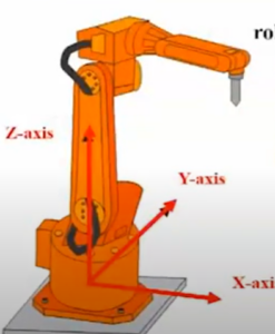
World Frame
The world frame is attached to the base of the robot. This is also referred to as the Cartesian coordinate frame. This frame is perfect for defining comprehensive paths or safety boundaries, like when a robot operates inside a protective cage. By setting boundaries within the world frame, you can ensure safety and precise control.
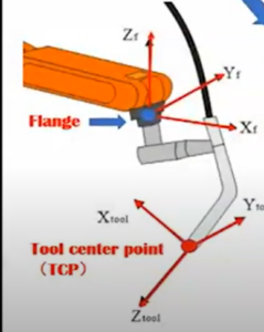
Tool Frame
The tool frame is attached to the end of the arm of tooling. This frame comes into play when you’re dealing with multiple tools on a robot arm. Consider a grease application robot, with two tools at its disposal: one for applying the grease and the other for camera inspection. By defining a unique frame for each tool, you achieve seamless transition between and precision control over individual tasks of the application.
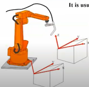
User Frame
User-defined frames accommodate strange shaped work pieces, like an inclined work surface (Image 1). It becomes very easy to program points along these surfaces if we define one of the axes along these inclined edges. User frames allow you to align the x, y, z coordinate system about a fixture or workpiece that is translated and/or rotated with respect to the world frame of the robot. Defining a user frame can considerably reduce programming efforts. In most simplistic example, for moving the robot from point A to B along the inclined edge of the object in Image 1, in world frame, would require at least 2 liner moves, as against in the user frame (defined with one of the axes along the inclined edge) would need just a single liner move.
Jog Frame
Jog frames are not very commonly used but are very similar to user frames. While not integrated into the robot program, jog frames serve as temporary frames established by the user to facilitate manual robot positioning from one point to another. These frames can be used during debugging or the initial commissioning of the robot, but are typically not needed in later phases. Jog frames simplify the process of manually guiding the robot for diagnostic and setup purposes, ensuring efficiency during critical stages of deployment.
Conclusion
When considering robot frames, it’s important to distinguish between permanent frames (world, user, and tool frames) and temporary frames (jog frames). Permanent frames, once established, streamline the programming and execution of robot moves. Jog frames are temporary, facilitating manual robot manipulation during setup and debugging.
Selecting the right frame becomes especially important when handling robot relocation or tool modifications. Programming in the world frame demands adjustments for every robot point. Programming in the tool frame allows a single adjustment to the tool frame to automatically update all points, significantly reducing labor and minimizing rework.
Selecting an appropriate robot frame is half the battle and if approached properly, it can save steps in programming and headaches later on. Take the example of relocating the robot from one place to another. If every move in the robot was programmed in world frame, after relocation every point would require adjustment. On the contrary, if the robot was programmed in the tool frame, just adjusting the frame would automatically adjust all the points.
If you’re looking for a good tool to work with when it comes to coordinating system frames, ROBOGUIDE allows engineers and operators to virtually explore and refine the alignment of different robotic components and workstations. By simulating these coordination tasks, users can identify and resolve potential issues, ensuring that the robot’s movements, tool paths, and actions are precisely synchronized with the target objects and processes.
Best of luck and let us know if you have any questions!

Editor’s Note: This post was originally published in April 2017 and has been updated for comprehensiveness and clarity.
Related categories: Blog Robotics