How to Save Time and Frustration When Configuring VFD Safety on Profinet
Blog post by Nikhil Niphadkar, Controls Engineer, Patti Engineering Texas Office
Industrial Engineering principle: “Do it right the first time”.

I have seen people, including myself, struggle while configuring safety functions with the Variable Frequency Drive (VFD) like SINAMICS G120s and G120Ds. If the correct procedure is followed, the VFD Safety can be configured and VFD can be online in no time.
The procedure here does not need a separate, specialized programming device to program the VFD.
Procedure: Configuring Variable Frequency Drive Safety
Configure the VFD
a. Add the appropriate VFD model in the hardware configuration of STEP7.
- Assign the (offline) IP address and the name to the device.
- Drag and drop appropriate PROFIsafe Telegram in the first module slot under the VFD.
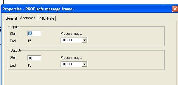
- By double clicking the PROFIsafe Telegram to open telegram properties pop-up. (Fig. 1)

Fig. 1 – Click to enlarge - Assign the input and output addresses under the Address tab.
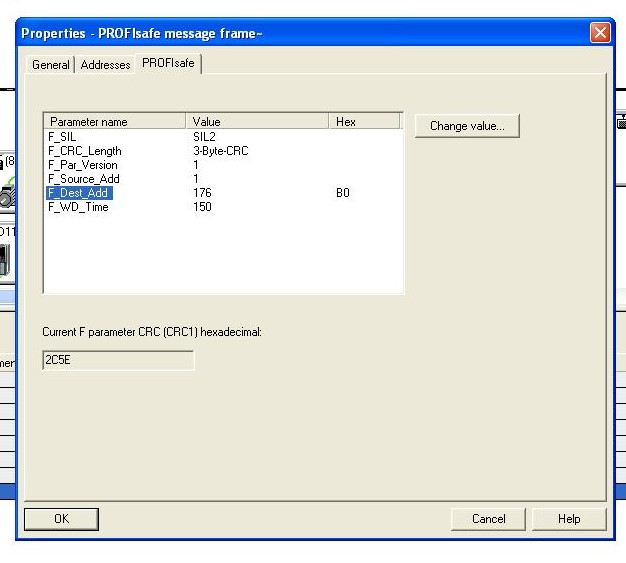
- Under PROFIsafe tab, the safety address i.e. F_Dest_Add can be assigned. (Fig. 2) This address will be entered later on in the Starter software in Step (f).

Fig. 2 – Click to enlarge - Close the pop-up box, save and compile, and download the hardware configuration to the PLC.
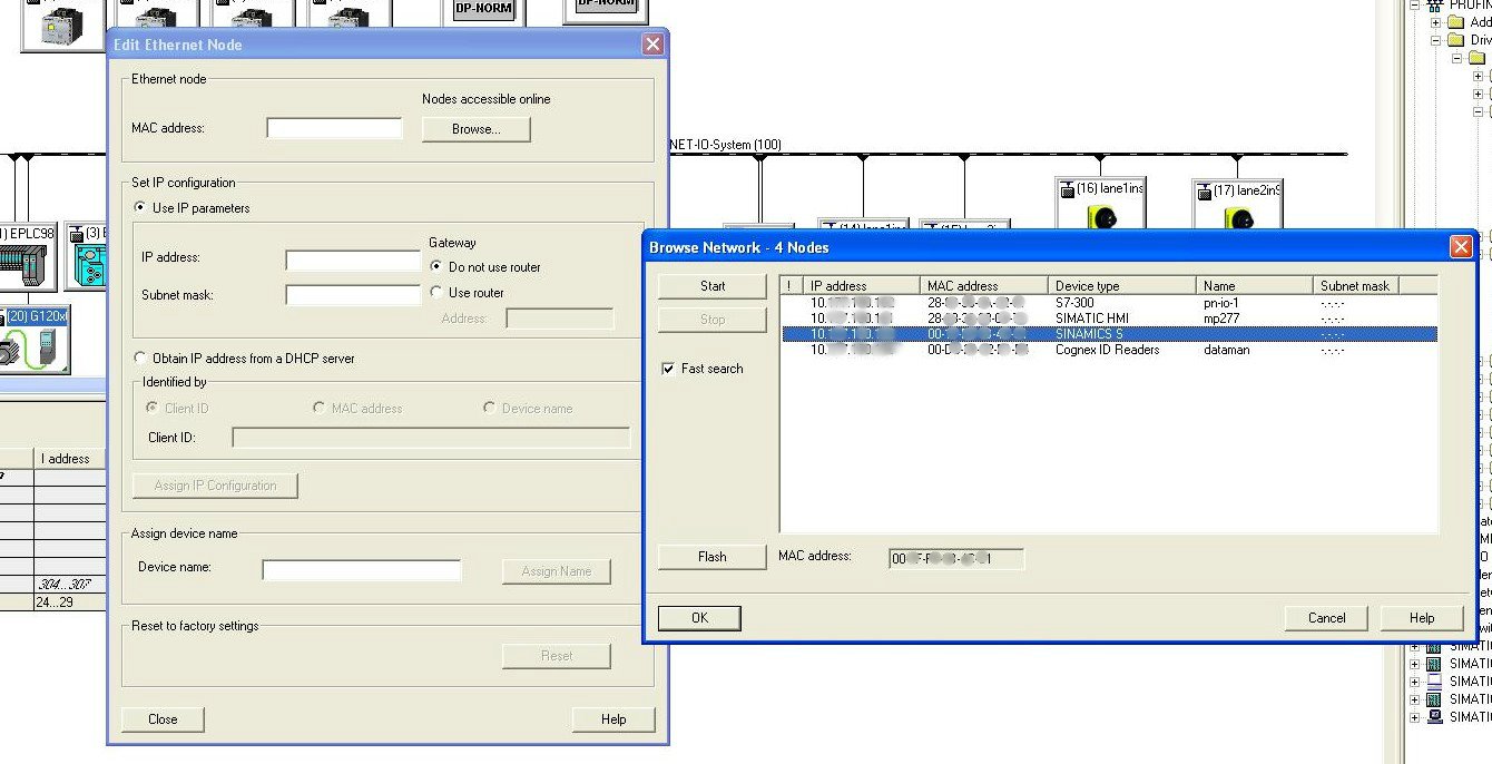
b. To configure the VFD, open Starter (software by Siemens) and search for accessible nodes. (Fig. 3*)
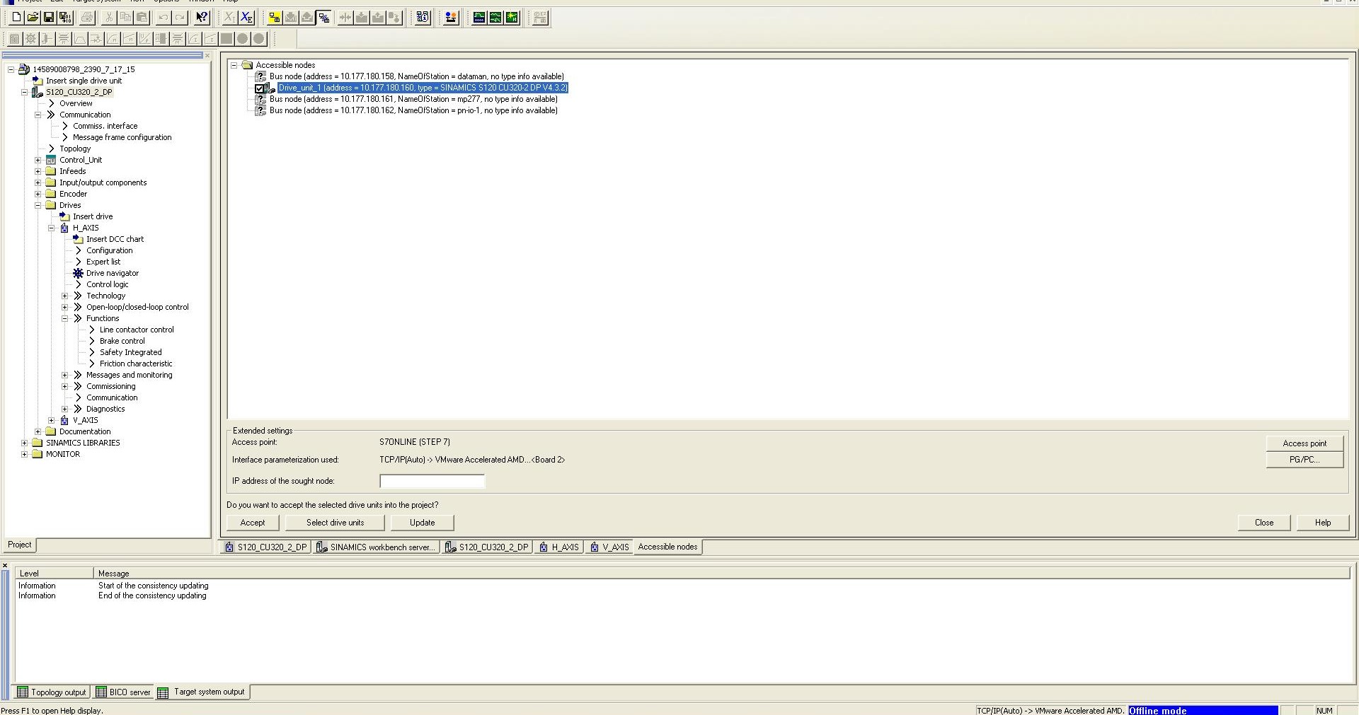
If the particular PLC is on a larger network of PLCs (say Profinet), it is always helpful to isolate the specific PLC (disconnect from the network), as it helps the software minimize the amount of time to search for accessible nodes.
c. Once the accessible nodes are found, choose the correct MAC address/IP address combination corresponding to the VFD/VFDs in question and add to the project. (Assuming that online IP address has been assigned to the VFD using regular STEP7 hardware configuration procedure: PLC→Ethernet→Edit Ethernet Nodes→Browse) After selecting the appropriate VFD using MAC address identification, assign IP address and name to the online device. (Fig 4*)
d. Go online with one VFD at a time. This ensures that you don’t accidentally make changes to the wrong VFD, if the project includes more than one. From here on, all the changes made to the VFD configuration are applied directly to the device since the changes are made while VFD is online.
Integrate Safety Functions
e. After all necessary set up for VFD (assigning correct motor parameters and appropriate VFD parameters), “Safety” functions can be integrated.
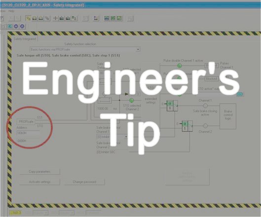
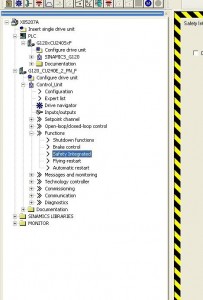
- The safety functions can be found under the specific drive’s menu tree (Control Unit→ Functions →Safety Integrated). (Fig 5)
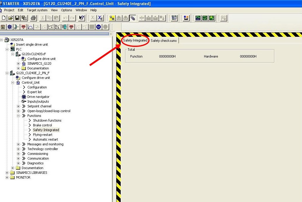
- On the “Safety Integrated” page, two tabs can be found, “Safety Integrated” and “Safety Checksum”. All the configuration will be done on “Safety Integrated” tab. (Fig 6)
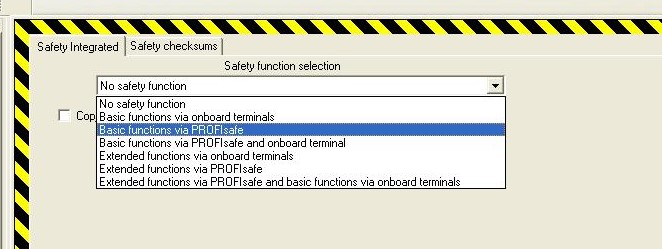
- The project specific Safety Function can be selected from the drop-down. (Fig 7)
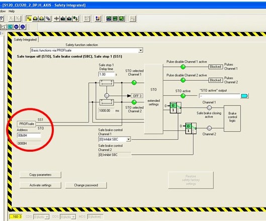
f. Once the appropriate safety function is selected, enter the F_Dest_add (F Destination Address or PROFIsafe address) in the address field provided on the Safety Integrated tab in Hex format. This address is the Safety Address you entered in the STEP7 hardware configuration under the properties of the PROFIsafe Telegram on PROFIsafe Tab in Step “a.” (Fig 8*)
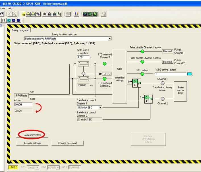
- Once this address is entered, hit “Copy Parameters” button on the lower left side of the screen. This will populate the un-editable field below the address field, with the same address that you entered in the address field. (Fig 9*)
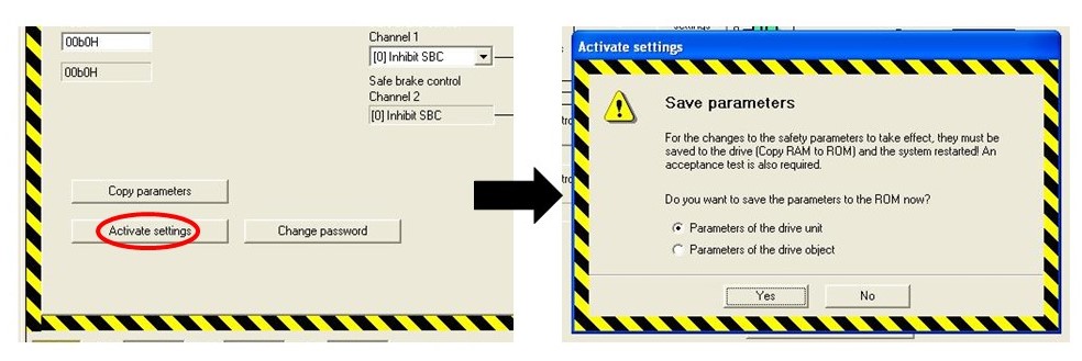
- Hit “Activate Setting” button.
- At the end of this procedure, a pop-up box will let you know that the settings have been applied successfully and give you an option (check box) to perform “Copy RAM to ROM procedure” (Fig 10). Alternatively, on the top menu buttons of Starter software, a shortcut button is provided to do the same.
- A quick check to ensure if the safety functions are configured correctly or not can be performed on the second tab, Safety Checksum, on Safety Integrated page. If the Checksum matches, it is safe to assume that safety parameters have been applied correctly.
Cycle the power on the PLC and test
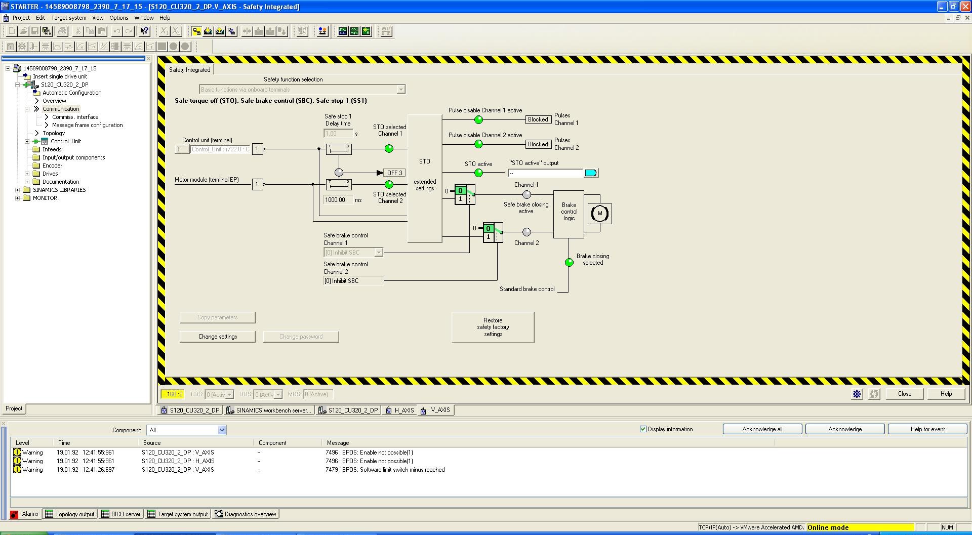
g. After following this procedure, an alarm will be generated saying “Acceptance Test Required”. This essentially means that the power must be cycled on the PLC and the main panel. This is necessary for the above changes to take effect. Acknowledge the alarm in Starter. (Fig 11*)

h. Cycle the power on the PLC and main cabinet. Once the PLC and all other devices are back up, the VFD should be talking to the PLC online and equipped with safety function.
i. Go online with the said VFD again (in Starter), and make sure there are no alarms or warnings under the Alarms tab. Once everything is confirmed, upload the online version of the program to your offline project and save. This will ensure that your online and offline programs match.
Configuration of VFD can be tedious if not done the right way. It can be time-consuming and frustrating if the VFD doesn’t communicate with the PLC after configuring the safety functions. Following above procedure guarantees that all steps have been performed to configure the safety functions with the VFD.
*=The images marked with this sign are taken from a configuration of a Servo (S120) and not a VFD. However, the basic underlying configuration procedure stays the same and these images do serve the purpose of demonstrating the steps. Please note that since these images are taken from a Servo configuration, the “Safety Checksum” tab is not available in the “Safety Integrated” screens.
Related categories: Blog Control Systems Integration