Using ROBOGUIDE for Robotics System Design
ROBOGUIDE is an offline software simulation tool developed by FANUC that allows users to design, simulate, and validate robotic systems within a 3D virtual environment. Every FANUC robot has been modeled in the software to accurately simulate and analyze the behaviors and capabilities of different robots, ensuring the selected robot is the best fit for the application and will function as intended.
Patti Engineering’s team uses ROBOGUIDE to support project planning, design, and implementation; this article highlights how we use the tool during a client’s project design and development phase to help them select the appropriate robot and configuration to meet project goals.
1. Verifying Cell Layout and Robot Reach
Verification helps determine that the selected robot has the required reach to perform the proposed tasks efficiently. When using ROBOGUIDE, we prefer the smallest robot possible for the operation, as smaller robots are faster.
Once you select a robot, ROBOGUIDE creates a 3D visualization of the spatial relationships between the robots and their surroundings. You can build a detailed model of the entire work cell layout, including fixtures, tables, machines, conveyors, and more, in ROBOGUIDE’s virtual 3D environment to accurately simulate and analyze the behaviors and capabilities of different robots and options, and address potential design issues.
For the project depicted in Figures 2 and 3, ROBOGUIDE allowed us to verify that the placement and reach of the proposed robots were suited to the application.
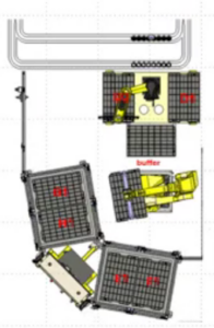
In this work cell, using ROBOGUIDE ensured that the selected robot (FANUC M-710/C) could reach the tray locations (top right) and both stacks of 10 trays in each tote. It also demonstrated the optimal placement of the robot for reachability.
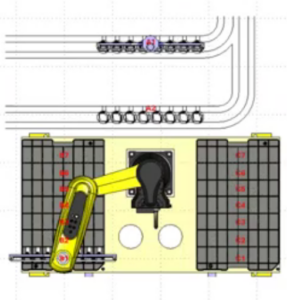
Close-up of the top left robot from Figure 1): ROBOGUIDE helped determine the best orientation for this robot, enabling it to reach all the trays to its left and right, as well as the two conveyors behind it.

3D simulation of a robotic work cell
2. Programming the Robot’s Paths
Path programming is accomplished using the same FANUC teach pendant interface used for programming physical robots. However, you can also program robotic paths using CAD models and part geometry as reference points, streamlining the design process and reducing the need for tedious manual programming.
For example, when tasked with dispensing a bead of sealant, the path can be created using the dispensing tool’s nozzle as a reference point. The spatial coordinates of the object receiving the sealant, in this case, the CAD model of a transmission case, are used to define the exact location where the sealant needs to be applied. This approach is much faster than manually teaching each point, and the program can be directly transferred to the physical robot.
Note: ROBOGUIDE is also useful when designing lines with multiple robot operations; the 3D environment can simulate all the robots working together with fixtures opening and closing, conveyors moving, etc.
Tip: Use Joint Moves
Joint moves are preferred over Cartesian-based moves because of their speed, overall system performance, and minimized cycle time. Deciding between fine and gross moves is important, as fine moves are used for tasks requiring high accuracy, such as deburring, where the robot must maintain a millimeter-level tolerance to effectively track and remove burrs. Comparatively, gross moves facilitate quick transitions between different areas of a work cell where precision is less critical, ensuring the robot performs tasks efficiently while maintaining accuracy where it matters most.
3. Setting Up Offline Programming
Once you’ve successfully simulated the necessary programs in ROBOGUIDE’s virtual environment, you can load these programs directly into the physical robot, saving system programming time.
The transition from a simulated environment to a real-world application depends largely on the nature of the task. With applications, such as a typical palletizing job, exact precision is not required. In these cases, very little touch-up of programming points in the field is needed. Similarly, tasks such as painting or spraying lubricants do not require a high level of location accuracy, making offline programming highly effective.
Tasks involving precise assembly of parts with minimal clearance often require manual programming to “touch up” final robot locations.
Note: Part variance presents some challenges, requiring more program adjustments to ensure accuracy. Precision becomes more important when working with parts that vary. For example, when deburring, precision is crucial because every part is slightly different.
4. Analyzing Cycle Time
Once a cell’s layout is complete and the robot’s operation is fully defined, ROBOGUIDE provides an accurate estimation of the robot’s cycle time. We often use ROBOGUIDE in the initial design of a cell to get a sense of the expected cycle time. For example, we recently used the software for a global medical technology company’s robotic cell. During the project’s proposal stage, we used ROBOGUIDE to show the client how long it would take the robot to load dunnage trays with eight test kits each. The tool helped us prove that we could meet the fast cycle time they required.
5. Evaluating System Lifespan
ROBOGUIDE provides insight into the robots’ longevity by identifying joints that may be overworked. The software calculates the forces, torques, and overall load at each robot joint, accounting for design parameters such as the programmed path and tool mass. Additionally, ROBOGUIDE calculates the duty cycle and average current use per joint, generating a report with this information, allowing you to assess the robotic system design for overall wear and tear.
6. Identifying Robotic Cell OEE Improvements
Whether your existing robotic system is experiencing downtime or you want to explore new ways to optimize production processes, ROBOGUIDE offers remote virtual simulation and validation without interrupting production. At Patti Engineering, if a client provides us access to their current robot program, we can typically identify opportunities to fix faults and suggest program changes that enhance OEE and overall performance, such as reducing rejects and improving cycle time.
Need Help Designing Your Robotic Cell?
Patti Engineering has extensive expertise in designing and integrating robotic cells. We’re proud to be trusted by industry leaders like FANUC. Visit our website to learn more about our past design work, or contact us today to schedule a project consultation.
FAQs
What Is ROBOGUIDE?
ROBOGUIDE is a FANUC-developed tool for designing, simulating, and validating robotic systems within a 3D virtual environment.
Does ROBOGUIDE Only Work With FANUC Robots?
Yes.
What Is ROBOGUIDE Used For?
Patti Engineering frequently uses ROBOGUIDE for:
- Application Verification: Confirming that the robot has the required reach for its intended task and that it fits within the proposed cell layout.
- Programming Paths: One or multiple robots can be programmed within the environment, and the programs can then be directly loaded onto the physical robot for offline programming.
- Analyzing Cycle Time & System Performance: ROBOGUIDE allows you to verify that your selected robot meets your cycle time goals and estimate its lifespan based on operational parameters.
- Identifying Improvements: After you’ve integrated your robot, you can use ROBOGUIDE to run ongoing simulations (without disrupting production) to identify potential improvements.
Will Programming Points Need to be Touched Up?
It depends on the robot’s assigned task. We recommend making adjustments as needed for applications with part variance or other applications where precision is critical.